
In the article Hybrid Rockets: An Overview we looked at the basic components of bi-propellant, mono-propellant, solid, and hybrid rocket motors. Now, we will take a closer look at the state of the art with respect to hybrid rocket motor design focusing on oxidizer and fuel grain options.
Oxidizers
All oxidizers for hybrids need to be in liquid form for it to be possible to reliably inject them into the motor. Some bench-testing had been done with gases, but in the vast majority of cases liquids are used.
I know of no one who has attempted to used nitrogen tetroxide, but doubtless, someone, somewhere, has tried it.
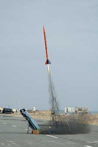
This Seri 3 sounding rocket launched by students from NASA’s Wallops Island uses uses a solid thermoplastic fuel grain and liquid nitrous oxide as oxidizer (Credits: NASA).
Nitrous Oxide (N2O)
The most popular oxidizer for amateurs and many professionals has been nitrous oxide, because it will self-pressurize from a saturated state at atmospheric temperatures. This removes the need for pumps and external pressurization. This is, however, a crude approach that has its own problems. The boil-off pressure varies with temperature and, often, the ullage (space in the oxidizer tank occupied by gas) has to be heated to bring up the pressure to give the desired flow-rate for the motor’s design. Nitrous oxide gas is susceptible to deflagration/detonation from a variety of ignition sources. In rocketry, adiabatic compression (dieseling or ‘water hammer’) can occur from events in the rest of the system, including hard-starts, back-shock from a running motor or a loss of pressure differential across the injector. This phenomeon can initiate an explosive decomposition event. This danger is present even when the system is being filled, idle but filled, or in a ‘cold flow’ where liquid N2O is fed into the system without ignition. When a self-pressurized system is activated, pressure in the vessel will drop and the N2O will commence to boil.
Boiling liquids produce gas-pockets throughout their entire volume. As the supply to the motor boils, it becomes compressible. This causes the classic ‘pulsing’ often observed in N2O hybrid rockets, and it makes injection less stable and harder to predict and control.
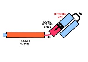
The alternative to self-pressurization, is to fill the ullage with an inert gas to provide pressure and to prevent the N2O from boiling and creating compressible N2O gas. This has the added advantage of delivering a non-compressible liquid to the injector. As the vessel empties, however, the gas can find its way through the liquid and reduce performance or extinguish the motor. A dip-tube in the vessel can minimize this effect. Commonly, nitrogen is used as the pressurant gas, but it will dissolve over time into the N2O and reduce performance. Other gases such as helium, argon, and even oxygen have been used. There is some suggestion that helium causes foaming which could reduce performance. Pressure can be maintained, as the vessel empties, by feeding pressurant gas from an external pressurant tank. A high flow regulator will keep the push-pressure constant, which makes for a smoother and more predictable performance.
Simple schematic of a positive displacement system (Credits: Carolynne Campbell-Knight).
Another method, known as positive displacement, involves more complex engineering. It uses a piston or bladder to separate the push gas from the liquid N2O. This results in a very smooth and predictable performance, and does away with the problem of pusher-gas being dissolved into the N2O. If the system is pre-pressurized prior to filling with N2O, it is possible to avoid boiling entirely. No free N2O gas is formed and the explosion risk is greatly reduced.
All materials have more than the classic three phases of state, solid, liquid, and gas. There is also the supercritical state, which occurs when temperatures exceed a certain chemical-specific critical point. For instance, the critical point of nitrous oxide is 36 degrees Celsius. At this temperature it becomes a supercritical fluid which is compressible and very sensitive to shock. Oxygen also has a critical point but this is reached at much lower temperatures, and must be avoided by deep refrigeration.
Nitrous oxide is a powerful solvent and it will dissolve hydrocarbon materials very readily. Solutions of nitrous oxide with hydrocarbons are many times more shock-sensitive than the pure oxidizer itself. Nitrous oxide can also be catalyzed into decomposition and explosion by many substances, notably iron oxide (rust). Great attention must be paid to all materials that will come into contact with N2O in a rocket system.
One other downside of nitrous oxide is that it is two-thirds nitrogen, which is dead-weight in oxidization terms. In a rocket motor system this results in a much lower specific impulse than liquid oxygen, which is pure oxidizer.
High-Test Hydrogen Peroxide (HTHP)
High-Test Hydrogen Peroxide (HTHP) is a highly corrosive and reactive compound that, again, has to be handled with great care, and for which materials compatibility is of great importance. It is a liquid that readily decomposes into water and oxygen. As a liquid, it cannot self-pressurize and must be pumped or pressure-pushed into the injector of a rocket motor.
When passed across a heated catalyst (usually silver oxide), HTHP decomposes rapidly and produces hot, high-pressure steam. It also frees an oxygen atom, which can be used to burn a fuel grain. In larger rockets with HTPB, it has proven difficult to get a burn established. Modifications to fuel grains and the addition of igniters have been tried, but with seemingly limited success. Daniel Jubb, in the UK is developing a large motor using HTHP and a modified HTPB fuel grain for the Bloodhound jet/rocket powered car. Jubb has found it needful to include an oxidizer, ammonium perchlorate, in the fuel grain. This has resulted in some problems including difficulty in extinguishing the motor.
– In the video below, BLOODHOUND Tests Europe’s Largest Hybrid Rocket (77,000 thrust hp)
[cleveryoutube video=”hBv6-9nLr2s” vidstyle=”1″ pic=”” afterpic=”” width=”” quality=”inherit” starttime=”” endtime=”” caption=”” showexpander=”off” alignment=”left” newser=””]

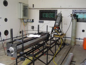
Test firing an American Rocket Company (AMROC) hybrid rocket motor at NASA’s Stennis Space Center in 1994 (Credits: NASA).
Liquid Oxygen
Many of the earlier experimenters, including NASA and AMROC, amongst others, employed liquid oxygen. They were able to scale motors up to considerable sizes and get them to start reliably. There was an effort to make these motors into a suitable replacement for solid boosters on systems such as the Space Shuttle, the attraction being that they could be throttled and shut-down. While liquid oxygen proved an excellent oxidizer for hybrids, and it solved many of the problems encountered in scaling up from smaller motors, fuel grain problems doomed most of these efforts.
One notable exception is the Space Propulsion Group, where novel paraffin fuel grains, combined with liquid oxygen, have performed well and produced impressive specific impulses. They have ameliorated the problems of handling a cryogenic oxidizer, by using of a solution of nitrous oxide in liquid oxygen, raising the cryogenic temperatures to around minus 45 degrees Celsius. This liquid, as with liquid oxygen, must be pumped or pressure-pushed, which presents other technical challenges which are by no means insurmountable. Materials compatibility issues must still be addressed.
Fuel Grains
When it comes to fuel grains, it is fair to say “If it will burn, we’ll try it!” Amateurs and professionals have tried everything from sugar, to paper to sausage (yes – sausage!!!). The basic principal for a hybrid fuel grain is: put a hole down the middle, feed it some oxidizer, and light it.
– In the video below, a salami-powered hybrid rocket engine.
[cleveryoutube video=”i0zon3xOaI4″ vidstyle=”1″ pic=”” afterpic=”” width=”” quality=”inherit” starttime=”” endtime=”” caption=”” showexpander=”off” alignment=”left” newser=””]
Fuel grains have been the most problematic area of hybrid rocket design. With truly solid fuel grains there have always been difficulties with ignition, optimum fuel-to-oxidizer ratios, and regression (the rate and pattern of fuel consumption). As with a solid rocket motor (with an oxidizer port down the middle), the surface of the fuel grain burns away increasing surface area. This affects chamber pressure and fuel-to-oxygen ratios. In a hybrid, the fuel grain does not support its own combustion (or perhaps one should say “should not support its own combustion”).
The most used fuel has been HTPB, which is a combustible long-chain polymer that has long been used as a binder and fuel in solid rocket motors. The use of HTPB has often been ‘received wisdom’ and, often, its suitability for this application has not been questioned. Amateur rockets, both commercially produced and home-built, tend to use HTPB almost exclusively. It works quite well in smaller rockets. However, problems have been encountered when scaling up to motors with thrust in the thousands of pounds range. It was found hard to initiate combustion, and it was necessary to go beyond a simple cylindrical port along the fuel grain, in order to improve surface area and fuel-grain regression (consumption). Hybrids with HTPB fuel grains tend to run ‘lean’ (oxygen rich), which can result in high run temperatures that damage nozzles and other components.

Different configuration of fuel grain port in different configurations is an important aspect of hybrid rocket motor design that can yield different burn characteristics. Noncontinuous regions and brittle edges can cause complications.
Fuel grains are cast with a hole down the long axis just like the ports in solid rocket motors. Many different cross-sections for the bore geometry have been tried, including inverted stars and wagon-wheels. If a geometry is selected that creates non-continuous regions within the fuel grain, separate injectors are required for each passage-way through the motor. Fuel grains now became more complex and expensive to produce. The more intricate the shape, the greater the danger of lumps of HTPB coming loose as structures get burned away. This results in ejection of lumps and sometimes nozzle blockage, which can be catastrophic.
It is very difficult to cast a large fuel grain with an entirely consistent shape and density. As a result, one port will generally burn faster than another, giving an uneven and inefficient burn. Hot-spots along the length of a fuel-grain are also common, leaving behind a tell-tale wavy longitudinal cross-section.
A few of the groups working in Hybrid rockets have abandoned HTPB and other solid polymers in fuel grain design. Notably, Space Propulsion Group is employing paraffins which vaporize into the heart of the motor, removing the need for exotic cross-sections and castings, and the need for multi-point injector assemblies. They have found a huge increase in reliability, performance and more reliable and faster ignition, thereby avoiding hard-starts. Autodiverse, in the UK, is using a cellulose wick soaked in kerosene to achieve similar outcomes.
Those who are persevering with HTPB, have, in many cases, had to resort to ‘doping’ fuel grains to overcome ignition and regression problems. Doping usually involves including oxidizers, such as ammonium perchlorate, and more energetic fuels, such as powdered aluminium or iron oxide.
While helping to address the problems of ignition and regression, other problems surface when this approach is used. With oxidizer in the fuel grain, ignition can occur beneath the surface of the grain. This can eject particles and lumps from the motor without being completely combusted and will result in a large ejection of soot and other particles. The addition of a chlorine-based oxidizer can result in chemical reactions that produce carcinogenic and poisonous substances – especially with partial combustion.
Test of an Autodiverse hybrid rocket at Airborne Engineering at Wescott (Credits: Autodiverse).
If too much of the doping materials are incorporated, it can be difficult, if not impossible, to extinguish the fuel grain. At this point it has crossed the barrier into the arena of solid rocket fuel grains and should be treated as an explosive and toxically hazardous material.
Conclusion
While hybrid rocket motors offer tantalizing prospects for simple and low-cost rocket propelled vehicles, their promise has yet to be realized. Those motors that are using truly evaporative fuel grains perhaps should no longer be classified as ‘Hybrids’ but rather as a variation of a liquid-fuelled bi-propellant motor. Autodiverse refers to its kerosene-wick motor as a ‘Bi-bryd’.
– Carolynne Campbell-Knight


![A trajectory analysis that used a computational fluid dynamics approach to determine the likely position and velocity histories of the foam (Credits: NASA Ref [1] p61).](http://www.spacesafetymagazine.com/wp-content/uploads/2014/05/fluid-dynamics-trajectory-analysis-50x50.jpg)


Great article, very thorough regarding HTPB. Any info on polyamides? That was the propellant used in the motor of the Spaceship 2 fatality.
We got back in touch with Carolynne, the author, to get additional information. Stay tuned!
– Carolynne Campbell-Knight – Probably the best article on hybrid type solid fuel rocket motors I have had the pleasure to read. It provides a realistic understanding of the propulsion issues Virgin Galactic is dealing with. I had seen Carolynne’s statements of concern about the safety of the failed test quoted in stories on Parabolic Arc, but she was never identified by the author. I was as interested then as now to know her credentials and involvement with the program.
– State of the Art – Novel InFlow Tech – Featured Project Development;
1-Gearturbine, 2-Imploturbocompressor
1-GEARTURBINE PROJECT
Rotary-Turbo-InFlow Tech
Atypical InFlow Thermodynamic
Technology Proposal Submission
Novel Fueled Motor Engine Type
*State of the art Innovative concept Top system Higher efficient percent.*Power by bar, for Air-Planes, Sea-Boats, Land-Transport & Dynamic Power-Plant Generation.
-Have similar system of the Aeolipile Heron Steam device from Alexandria 10-70 AD. -New Form-Function Motor-Engine Device. Next Step, Epic Design Change, Broken-Seal Revelation. -Desirable Power-Plant Innovation.
YouTube; * Atypical New • GEARTURBINE / Retrodynamic = DextroRPM VS LevoInFlow + Ying Yang Thrust Way Type – Non Waste Looses
-This innovative concept consists of hull and core where are held all 8 Steps of the work-flow which make the concept functional. The core has several gears and turbines which are responsible for these 8 steps (5 of them are dedicated to the turbo stages). The first step is fuel compression, followed by 2 cold turbo levels. The fourth step is where the fuel starts burning – combustion stage, which creates thrust for the next, 5th step – thrust step, which provides power to the planetary gears and turbines and moves the system. This step is followed by two hot turbo steps and the circle is enclosed by the final 8th step – bigger turbine. All this motion in a retrodynamic circumstance effect, wich is plus higher RPM speed by self motion. The Reaction at front of the action.
*8-X/Y Thermodynamic CYCLE – Way Steps:
1)1-Compression / bigger
2)2-Turbo 1 cold
3)2-Turbo 2 cold
4)2-Combustion – circular motion flames / opposites
5)2-Thrust – single turbo & planetary gears / ying yang
6)2-Turbo 2 hot
7)2-Turbo 1 hot
8)1-Turbine / bigger
-With Retrodynamic Dextrogiro vs Levogiro Phenomenon Effect. / Rotor-RPM VS InFlow / front to front; “Collision-Interaction Type” – inflow vs blades-gear-move. Technical unique dynamic innovative motion mode. [Retrodynamic Reaction = When the inflow have more velocity the rotor have more RPM Acceleration, with high (XY Position) Momentum] Which the internal flow (and rotor) duplicate its speed, when
activated being in a rotor (and inflow) with [inverse] opposite Turns. The Reaction at front of the action. A very strong Novel torque power concept.
-Non waste parasitic looses for; friction, cooling, lubrication & combustion.
-Shape-Mass + Rotary-Motion = Inertia-Dynamic / Form-Function Wide [Flat] Cylindrical shape + positive dynamic rotary mass = continue Inertia positive tendency motion. Kinetic Rotating Mass.
-Combustion 2Two continue circular [Rockets] flames. [ying yang] opposite one to the other. – With 2TWO very long distance INFLOW [inside propulsion] CONDUITS. -4 TURBOS Rotary Total Thrust-Power Regeneration Power System. -Mechanical direct 2two [Small] Planetary Gears at polar position. -Like the Ying Yang Symbol/Concept.
-The Mechanical Gear Power Thrust Point Wide out the Rotor circumference were have much more lever [HIGH Torque] POWER THRUST. -No blade erosion by sand & very low heat target signature profile. -3 points of power thrust; 1-flow way, 2-gear, 3-turbine. *Patent; Dic. 1991 IMPI Mexico #197187 All Rights Reserved. Carlos Barrera.
—————————————
·2-Imploturbocompressor; One Moving Part System Excellence Design – The InFlow Interaction comes from Macro-Flow and goes to Micro-Flow by Implossion – Only One Compression Step; Inflow, Compression and outflow at one simple circular dynamic motion Concept.
*·“Excellence in Design” because is only one moving part. Only one unique compression step. Inflow and out flow at the same one system, This invention by its nature a logic and simple conception in the dynamics flow mechanics area. The invention is a wing made of one piece in a rotating motion, contained in a pair cavity system connected by implocavity, and interacting dynamically with a flow, that passes internally “Imploded” through its simple mechanism. This flow can be gas (air) or liquid (water). And have two different applications, in two different form-function; this one can be received (using the dynamic flow passage, as a receiver). Or it can be generated (with a power plant, generating a propulsion).
An example cut be, as a Bike needs a chain to work from motor to wheel. And for the Imploturbocompressor application, cut be as; in a circumstance at the engine, as an A-activate flow, and with a a tube flow conduit going to the wheel as a B-receiving-flow the work use.
To see a Imploturbocompressor animation, is posible on a simple way, just to check the Hurricane Satellite view, and is the same implo inflow way nature.
And when the flow that is received and that is intended to be used at best, must no necessarily by a exhausting or rejection gas, but must be a dynamic passing gas or liquid flow with the only intention to count it or to measure it. This could be possible at the passing and interacting period when it passes inside its simple mechanism. This can be in any point of the work flow trajectory.
In case the flow that is received is a water falling by gravity, and a dynamo is placed on the rotary bar, the Imploturbocompressor can profit an be obtained by generating? electricity such as obtained by the pelton well, like I say before. The “Imploturbocompressor”, is a good option to pump water, or a gas flow, and all kinds of pipes lines dynamic moves.
Or only receive the air-liquid flow, in order to measure its passage with a counter placed on the bar, because when this flow passes through the simple mechanism of a rotating wing made of only one piece it interacts within the implocavities system. And this flow can be air wind, with the difference of can have an horizontal work position, and that particle technical circumstances make an easy way for urban building work new use application, and have wind flow from all the sides 180 grades view. The aforementioned information about this invention refers to technical applications, such as a dynamic flow receiver. (whether being gas or liquid).
With the appropriate power plant and the appropriate dimensioning and number of RPM this invention is also feasible to generate an atmospheric air propulsion and the auto-propulsion of an aircraft. Being an effective and very simple system that implodes and compresses the atmospheric air permits the creation of a new concept of propulsion for aircrafts, due to its simple mechanism and innovative nature. At the place of the aircraft were the system appears and the manner how the propulsion direction can be oriented with a vectorial flow (no lobster tail) with I call “yo-yo system” (middle cut (at the shell) to move, one side loose), guided and balanced is feasible to create a new concept of TOVL-vertical take-off landing, I wish good for a wild conditions. Because the exhaust propulsion can going out radial in all the 360 vectorial positions, going out direct all the time in all the vectors direction. With his rotor cover for an better furtive fly, like going down of a bridge for example.
Likewise, with the due form and dimensioning, and considering the liquid density and the due revolutions for this element there could be generated a propulsion (water) in order to move an aquatic ship, whether on surface or under water. Also can be a good option to pump liquid combustion for a rocket propulsion.
Making a metaphoric comparison with the intention to expose it more clearly for a better comprehension of this innovative technical detail, it would be similar to the trajectory and motion of a dynamic flow compared with a rope (extended) that passes through the system would have now a knot (without obstructing the flow), so the complete way of the flow at the imploturbocompresor system have three direct ways and between make two different turns; direct way (entrance) – turn – direct way (implocavity) – turn – direct way (exit), all this in a 1 simple circular move system concept.
Its prudent to mention that the curves and the inclinations of the blades of a rotating wing made of this invention, is conferred by its shape and function a structural rigidity allowing it to conduct and alter appropriately the dynamic flow passing through its system.
The author should research a little more as the statements about peroxide oxidiser in hybrids is not inline with broader industry knowledge. Peroxide has been demonstrated very successfully in hybrids since the 1960s with wide variety fuels from polyetheylene through to paraffin recently. Nammo Ronfus in Europe is building sounding rockets using peroxide oxidiser hybrids, after attempts to get LOX working. This oixidiser is frequently overlooked due to negative hysteria generated in the 60s by groups advocating for hydrazine, many programs used it quite safely including the Bristish. Not to mention also the massive industrial base for this chemical feeding into the paper & pulp industry. Its a shame to see it always dismissed so quickly as too difficult to handle, when less technical industries than ours can handle mega tonnes every year without incident?
Does this mean I can power a rocket with a pile of old math homework?